News
How our 3D laser scanning can improve ferry refurbishment times in Canada


Action

- Applied Precision 3D obtained access to the ferry's rudder and stock at Toronto Drydock.
- Safety training was provided to the scanning crew.
- The scanning team was given unrestricted access to the ferry to complete the all required 3D measurements.
- Leica HDS LiDAR scanners were used to capture the exterior of the hull.


Data Processing
- The point cloud data was aligned to a 3D coordinate system for easy analysis and manipulation.
- The 3D data was processed and final model prepared for the BYD Naval Architecture Team.

Results
- BYD obtained a highly accurate and detailed digital point cloud of the Ongiara ferry hull and rudder shaft.
- The model enabled faster and more precise design and engineering work.
- The 3D data could be used for a variety of applications, such as generating construction drawings, Fabrication drawing, CNC machining, creating virtual simulations, and performing 3D printing.
- The collaborative efforts of Applied Precision 3D and BYD Naval Architecture will keep the ferry running all year long to serve the visitors and residents.

Revitalize marine assets seamlessly with Applied Precision 3D
Our 3D expertise ensures precision refurbishment, efficient maintenance planning, and innovative 3D metrology. Elevate your maritime ventures with us.
How Applied Precision 3D Powered McMaster Solar Car’s Success?
Introduction
McMaster University Solar Car, a club dedicated to solar-powered vehicle innovation, aimed to participate in the American Solar Car Challenge with a lightweight carbon fiber vehicle. Recognizing the importance of accurate 3D data and precise tolerances in their design process, McMaster Solar Car sought assistance from Applied Precision 3D. This case study highlights how Applied Precision's 3D scanning services enabled McMaster Solar Car to streamline their design and reduce cost.
The Challenge
With their ambitious goal of creating a lightweight carbon fiber vehicle, the McMaster Solar Car Team faced the challenge of achieving precise tolerances and accurate part designs. To ensure optimal performance and efficiency, they needed reliable 3D data for their master assembly and part design.
Collaboration with applied precision 3d
Applied Precision 3D stepped in to support the McMaster Solar Car Team by providing high-accuracy 3D scanning services. Components such as the steering rack, wheel hub, and pedal mount were 3D scanned using advanced structured light 3D scanning technology, resulting in scan data aligned with an impressive accuracy of up to 25 microns (comparable to the thickness of a single strand of human hair).
Benefits Of 3d sCANNING
By utilizing Applied Precisions' 3D scanning capabilities, the McMaster Solar Car Team gained the ability to incorporate real-world part measurements into their custom designs. This eliminated the need to spend resources on test parts and saved valuable time that would have otherwise been spent on designing components from scratch. The accurate 3D scan data enabled the McMaster Solar Car Team to design their vehicle with confidence, ensuring precise fit and optimized performance.
Cost saving and efficient design
Experimental design can be a costly and time-consuming process. However, with the assistance of Applied Precision 3D, the McMaster Solar Car Team significantly reduced their expenses by eliminating the need for expensive test parts. By leveraging 3D scanning technology, the McMaster Solar Car Team achieved efficient design iterations, accurately 3D modeling their components, and optimizing their vehicle's overall performance.
Conclusion
The collaboration between Applied Precision 3D and the McMaster Solar Car Team demonstrates the significant impact of high-accuracy 3D scanning on design efficiency and cost savings. Applied Precision's expertise in providing precise 3D scan data allowed the Team to incorporate real-world measurements into their custom designs, eliminating the need for costly test parts. By streamlining their design process, the Team was able to focus on innovation and successfully participate in the American Solar car challenge.


Your 3D Experts Since 1999
Ready to Take Your Manufacturing to the Next Level?
Rusty Dream into a Bugatti Beauty – Famous Canadian Gamer/Animator ZMDE Inc
Introduction
ZMDE Inc, a renowned Canadian YouTuber led by Steven Song (on-screen name), embarked on an exciting project to create a Bugatti from scrap. Seeking professional assistance, ZMDE Inc approached Applied Precision 3D, a leading provider of 3D scanning services, reverse engineering, 3D CAD modeling, Quality Inspection.
This case study highlights the collaboration between the two teams and their journey to create a stunning Bugatti replica using 3D advanced technology.
Hold onto your hats, folks! This case study is about to blow your mind
And hey, if you find yourself desperately in need of some 3D Scanning and 3D CAD modeling magic, Give us a shout, we promise to leave you spellbound!
Case Study
Back ground
ZMDE Inc, known for their creative content and unique ideas, aimed to captivate their audience by constructing a Bugatti car from scratch. To achieve this, they required accurate 3D scanning of a 1:14 scale Bugatti. ZMDE Inc recognized Applied Precision 3D as a reliable partner with expertise in 3D scanning services, leading to their visit to Applied Precision 3D’s office in Vaughan, ON.
Collaboration and Process
Applied Precision 3D’s team of 3D application experts, Baily Nemorofsky and Aryan Patel, warmly welcomed ZMDE Inc's creative director Liam and Steven Wong. They facilitated the 3D scanning process, utilizing a Structured Blue Light Scanner and Aesub Spray for precise measurements and data capture. With coordinated efforts, the team successfully completed the 3D scanning of the Bugatti, resulting in accurate digital representations.

Filming The Youtube Episode
During the collaboration, ZMDE Inc took the opportunity to film a YouTube episode at Applied Precision 3D shop.
Steven Song was amazed by the quality of the 3D scanning results. Additionally, Q&A video clips were recorded, allowing Steven Song to inquire about the 3D technology employed by Applied Precision 3D and how the scanned file could be optimized for ZMDE Inc's final project.

ProfessionalAdvice and Interaction
Applied Precision 3D’s CEO, Robert Bell, actively engaged with ZMDE Inc's team, providing insights into the ZMDE project.
The discussion involved exploring the potential of 3D printing and maximizing the benefits of the 3D scanned file. ZMDE Inc valued the professional advice and expertise offered by Applied Precision 3D, further strengthening the collaboration, and building a positive rapport.
OngoingProject and Future Updates
The Bugatti Creation Revealed on YouTube generating significant excitement within both ZMDE Inc and Applied Precision 3D.
As ZMDE Inc successfully completes the creation of the Bugatti, Applied Precision 3D is excited to announce the release of the corresponding YouTube video that documents this remarkable achievement. With the Bugatti project now showcased on YouTube, Applied Precision 3D is eager to share updates with its audience, highlighting the fruitful collaboration and the revolutionary capabilities of 3D scanning technology.


Conclusion
The collaboration between ZMDE Inc and Applied Precision 3d exemplifies the value of professional 3D scanning services in creative content creation of Bugatti from scrap. By utilizing 3D advanced technology, ZMDE Inc embarked on an innovative project to create a Bugatti from scrap, with Applied Precision 3D playing a crucial role in providing accurate 3D scanning expertise. This case study demonstrates the successful partnership between the two teams and highlights the positive interaction, professional advice, and future prospects of this completed projects.
Applied Precision 3D
Discover more about us and our services from below
Why Did Blue Water Baits Choose 3D Scanning to Redefine Fishing Lures?
Amidst the competitive fishing lure industry, Blue Water Baits set out to redefine their product development process. This case study uncovers their journey to success, where 3D CAD modeling became the catalyst for ground-breaking innovation.
The Challenge
Blue Water Baits, a leading manufacturer of fish lures, sought to enhance their product development process by leveraging advanced 3D scanning technology. The challenge was to accurately digitize and create 3D CAD models of two lure bodies, ensuring precision and symmetry in their designs.
Action Steps
To address this challenge, Blue Water Baits collaborated with Applied Precision 3D, Canada's leading provider of 3D scanning and 3D modeling services. The following critical steps were followed:
Challenge Definition
Applied Precision 3D conducted a detailed assessment to understand the requirements and scope of the project, ensuring a seamless execution.
3D Scanning
Zeiss structured light technology captured the complex organic lure geometry. AESUB 3D scan spray ensured excellent data quality. Careful positioning ensured feature capture
Data Processing & CAD Creation
The 3D scan data was aligned using Polyworks, transformed into hybrid CAD models using as-built & NURBS techniques. Mirroring ensured symmetry, with precise modeling of intricate details
Results
The collaboration between Blue Water Baits and Applied Precision 3D yielded remarkable results, revolutionizing the product development process. Here are the key outcomes:
Precise Digitization
Applied Precision's 3D scanning provided accurate geometry capture, enabling BLue Water Baits to analyze designs virtually.
Enhanced Design Efficiency
Hybrid CAD models enabled efficient design iterations, streamlined development, and improved efficiency for Blue Water Baits.
Seamless Collaboration
Applied Precision 3D expertise and communication skills ensured a smooth collaboration, helping Blue Water Baits achieve project success.
Time and Cost Saving
3D scanning technology saved Blue Water Baits time and costs by eliminating manual measurements and reducing prototyping iterations.


CONCLUSION
The integration of 3D scanning technology into Blue Water Baits' product development process, in collaboration with Applied Precision 3D, marked a significant milestone in their pursuit of excellence. The accurate digitization of muskie lure bodies and the creation of precise hybrid CAD models provided Blue Water Baits with a powerful tool to innovate, refine, and deliver exceptional muskie lure performance to their customers. This successful case study demonstrates the transformative impact of 3D scanning technology and expertise on the fishing lure industry, paving the way for future advancements in product design and development.
Your 3D Experts Since 1999
Ready to Take Your Manufacturing to the Next Level?
Build a Digital Plant with 3D Plant Layouts to Drive Efficiencies
In a modern, advanced manufacturing plant, space needs to be used efficiently, including the allocation of work cells, production lines, machinery, and people. This can be extremely challenging. In the current economy, production plants also bear higher costs of industrial space due to rising real estate prices. When your workplace demands efficient and optimal processes, using a digital 3D plant layout model can define opportunities for better space utilization, workflows, and improved safety to boost overall asset utilization rates and ROIs.
3D Plant Layout vs 2D Drawings
Traditionally, engineers have been using 2D drawings to design plant layouts based on hand-measured metrics. When plant design becomes more complex, lacking the vertical dimension makes it hard to position the placement accurately.
Compared to 2D models and drawings, an "as-built" 3D model provides more structural engineering information, such as overhead clearances, elevations, and structural integrity.
3D plant layout of a manufacturing production line
How is a 3D Plant Layout created?
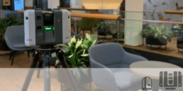
With unparalleled speed and accuracy, 3D laser scanning is a non-intrusive way to capture entire plants, production lines, work cells, equipment, and operator workspaces in full detail. With a state-of-the-art 3D laser scanner, our 3D experts capture as many views as the project scope requires around the site. The manufacturing plant is recorded as 3D point cloud data and can later be used to build an “as-built” 3D CAD model.
What value does a 3D Plant Layout provide?
With detailed, accurate 3D information, the complex industrial space, processes, and people workspaces are accurately represented in the 3D plant layout, offering key information on where workflow and space utilization improvements can be made. For plant expansions and change planning, changes can be applied in the virtual 3D environment to readily simulate additions and movements in the physical world. This ensures fitment and prevents downtime from errors in changes.
Benefits of Deploying 3D Technology & Expertise to Plant Design & Workflow
- Create, modify, and validate plant designs and layouts
- Digital simulation of the movement or addition of people, furnishings, and equipment that would fit in the current space and optimization relative to planned improvements
- Optimize existing plant layout and processes
- Create a “Digital Twin” to understand, monitor, and predict the physical asset
Check out our full list of manufacturing 3D services, also 3D scanning services for manufacturing plant and use our 3D expertise today.
Photo Credit: Leica-geosystems.com.
3D Expertise to Exceed Today’s Building Standards
Let us get you started by filling the adjacent form.
[tcb-script type="text/javascript"] var ss_form = {'account': 'MzawMDG3sDSwBAA', 'formID': 'M04xMzYxNk3RTTE2sdQ1MbJM1U00SrPUNUtKNk42N0szNEoxBAA'}; ss_form.width = '100%'; ss_form.domain = 'app-3QNKSH0IDI.marketingautomation.services'; // ss_form.hidden = {'field_id': 'value'}; // Modify this for sending hidden variables, or overriding values // ss_form.target_id = 'target'; // Optional parameter: forms will be placed inside the element with the specified id // ss_form.polling = true; // Optional parameter: set to true ONLY if your page loads dynamically and the id needs to be polled continually.[/tcb-script][tcb-script type="text/javascript" src="https://koi-3QNKSH0IDI.marketingautomation.services/client/form.js?ver=2.0.1"][/tcb-script]
Reshaping Digital Workspaces for Today and Tomorrow with 3D Laser Scanning (LiDAR)
As we all work through the challenges of the new era post-pandemic, we will continue to rethink and reassess the use of workspace and plan for the future. This involves adjusting the ‘traditional’ office design and layout and adding new collaboration technologies and equipment to support employees and work processes. To design the digital workspace, office and other facility layouts need to be professionally measured and planned from fresh perspectives before the changes take place.
How to Transform the Workplace for the Hybrid Workforce?
Challenge: Lack of 'as-built' information for retrofitting
- Accurate and detailed 2D drawings or facility 3D ‘digital twins’ provide project stakeholders with the ‘as-built’ information for planning, designing, and building more adaptive spaces and layouts
- The original workplace drawings could have been inaccurate and out of date due to changes that occurred over many years, and no current digital drawings exist
Our Approach
LiDAR 3D scanning brings unmatched accuracy, detail and speed in capturing important 3D information from:
- Existing layouts, equipment locations and details, and infrastructure are located even in hard-to-reach places
- Visible structural, MEP, and HVAC system elements are readily captures
Deliverables
From the 3D scan data, our experts deliver the following outputs:
- 2D floor plans, 3D models, and BIM models reflecting the ‘as-built’ condition and change-ready
- Conduct clash detection – to identify if, where, or how two elements within the building may interfere with one another
- Digital simulation of the movement or addition of people, furnishings, and equipment that would fit in the current space and optimization relative to planned improvements
- Resolve potential clearance issues
Benefits of Applying 3D Digitization to the Office Retrofit Projects
- Fast, accurate creation of 2D floor plan & 3D models
- Enable digital office design and hybrid office use
- Allow architects, engineers, contractors, and building owners to work collaboratively with the data
- Improve utilization of the working space
- Create a “Digital Twin” of the office based on the data to understand, monitor, and predict the physical asset
Explore our full list of LiDAR 3D scanning services and use our 3D expertise today.
Photo Credit: Leica-geosystems.com, Vuforia.
3D Expertise to Exceed Today’s Building Standards
Let us get you started by filling the adjacent form.
[tcb-script type="text/javascript"] var ss_form = {'account': 'MzawMDG3sDSwBAA', 'formID': 'M04xMzYxNk3RTTE2sdQ1MbJM1U00SrPUNUtKNk42N0szNEoxBAA'}; ss_form.width = '100%'; ss_form.domain = 'app-3QNKSH0IDI.marketingautomation.services'; // ss_form.hidden = {'field_id': 'value'}; // Modify this for sending hidden variables, or overriding values // ss_form.target_id = 'target'; // Optional parameter: forms will be placed inside the element with the specified id // ss_form.polling = true; // Optional parameter: set to true ONLY if your page loads dynamically and the id needs to be polled continually.[/tcb-script][tcb-script type="text/javascript" src="https://koi-3QNKSH0IDI.marketingautomation.services/client/form.js?ver=2.0.1"][/tcb-script]
Top 5 3D Laser Scanning Applications in Construction
If not resolved in a timely manner, small deviations between the physical building and the original drawings can become serious issues, causing delays and material waste. Therefore, it is critical to have the ‘as-built’ building condition measured and checked against the drawings at every project stage.
3D laser scanning (LiDAR) provides quick, accurate 3D measurements of the building structures and elements. When it is deployed in different stages of construction, you can detect early construction issues and develop corrective solutions before they get worse.
Here are five 3D laser scanning applications that can help you overcome challenges during construction:
On-going Monitoring and Quality Assurance
The 3D laser scanner is ultra-portable and our crews are ready to be deployed on short notice at the construction site to check the site's condition at any time. Scanning captures the ‘as-built’ condition of the site as high-quality point-clouds. It can be referenced against the CAD drawing or the BIM model to check for discrepancies.
Checking Floor Flatness and Levelness
Lean on 3D laser scanning and our expert crews to measure the floor flatness (FF) and floor levelness (FL) of a concrete slab. Positive and negative deviations can be determined. This allows your team to interpret details on complex surfaces and develop corrective adjustments accordingly.
Verifying Complex Steel Structures
To ensure building quality, complex steel structures need to be verified during and after construction. With our 3D laser scanning equipped crews, the data captured from the structure can be used to validate the positional accuracy of existing building structures.
Clash Detection & Interference Checks
Clash detection identifies if, where, or how two parts of the building interfere with one another. A 3D laser scan of existing conditions helps identify potential clashes in the BIM model. For example, identify the potential penetrations when installing facades or any exterior envelopes to help reduce shop fabricator drawing revisions.
Installing Building Envelope
By 3D scanning the “as-built” condition of the structure or building facade, our 3D experts quickly generates the 2D and 3D drawings with the exact dimensions for the glass. cladding sizing and installed embed & anchor locations. Compared to traditional measurement, it is faster and easier to design, install, and retrofit complex glass, cladding, and curtain walls.
Learn how we can help your Team today.
Image Source: Leica-geosystems.com
3D Expertise to Exceed Today’s Building Standards
Let us get you started by filling the adjacent form.
[tcb-script type="text/javascript"] var ss_form = {'account': 'MzawMDG3sDSwBAA', 'formID': 'M04xMzYxNk3RTTE2sdQ1MbJM1U00SrPUNUtKNk42N0szNEoxBAA'}; ss_form.width = '100%'; ss_form.domain = 'app-3QNKSH0IDI.marketingautomation.services'; // ss_form.hidden = {'field_id': 'value'}; // Modify this for sending hidden variables, or overriding values // ss_form.target_id = 'target'; // Optional parameter: forms will be placed inside the element with the specified id // ss_form.polling = true; // Optional parameter: set to true ONLY if your page loads dynamically and the id needs to be polled continually.[/tcb-script][tcb-script type="text/javascript" src="https://koi-3QNKSH0IDI.marketingautomation.services/client/form.js?ver=2.0.1"][/tcb-script]
Top 5 Digitization and 3D Scanning Applications in Tooling
Today's product designs involve more complex features, therefore demanding higher precision, incredible detail, and faster problem-solving from tool and die makers while designing and building new tooling. Lean on 3D digitization, a faster and more reliable approach to support successful tooling design, tool builds and overall manufacturability of complex parts. Here are the 5 top 3D digitization applications in tooling:
Physical to Digital Model Creation
Reverse engineering bridges the gap between physical and digital designs. The process starts with high-precision 3D scanning of the physical object or tooling to provide accurate, clean, and high-resolution data. The deliverable is a 3D model that can be used for various design and quality applications.
Faster Designs and Iterations
High-resolution 3D data is the foundation for product design in the digital environment. The 3D model can be readily scaled up or down to adjust for overall product size. Key features are added and modified.
Tooling Production from 3D CAD Model
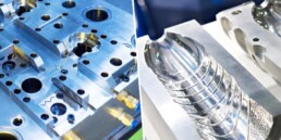
The model created from reverse engineering enables die, and mold production through all types of metal forming processes including casting, forging, and stamping, including 3D metal printing and CNC machining processes.
Tooling Inspection
When 3D data of the 3D-scanned part and the original 3D CAD are aligned, a comprehensive colour map inspection report can be produced to easily visualize deviations and extract critical quality measurements. The report indicates deviation values on specified inspection points and key features such as material thickness, clearance, and gap instances.
Wear Analysis and Repair
As tooling ages, part quality deteriorates and the risk of catastrophic failure increases. From the 3D model and colour deviation map, our experts identify tooling wear and reveal potential problematic areas proactively, including wear points, shrinkage and out of tolerance conditions. Preventive maintenance and repairs can be carried out quickly by knowing where the problems are.
Learn how we can help your Team today.
Ready to Take Tooling Excellence to the Next Level?
Let's get started with 3D metrology and reverse engineering.
[tcb-script type="text/javascript"] var ss_form = {'account': 'MzawMDG3sDSwBAA', 'formID': 'M04xMzYxNk3RTTE2sdQ1MbJM1U00SrPUNUtKNk42N0szNEoxBAA'}; ss_form.width = '100%'; ss_form.domain = 'app-3QNKSH0IDI.marketingautomation.services'; // ss_form.hidden = {'field_id': 'value'}; // Modify this for sending hidden variables, or overriding values // ss_form.target_id = 'target'; // Optional parameter: forms will be placed inside the element with the specified id // ss_form.polling = true; // Optional parameter: set to true ONLY if your page loads dynamically and the id needs to be polled continually.[/tcb-script][tcb-script type="text/javascript" src="https://koi-3QNKSH0IDI.marketingautomation.services/client/form.js?ver=2.0.1"][/tcb-script]
Case Study: Design Lighter Auto Suspension Components from Reverse Engineering
What is one of the first and most common challenges new automotive part design is likely to encounter?
Our answer is data.
While creating new designs from an existing part, the part's geometry or 3D CAD data is either outdated or unavailable. Historical math data can get lost or outdated—meaning not all the changes in the production tooling are captured in the existing CAD model. Thanks to high-precision 3D digitizing, comprehensive 3D data can be accurately acquired through reverse engineering the physical part.
The Challenge
Our customer, an automotive supplier, purchased some suspension components. They needed to optimize the existing design and conduct cost reduction analyses for a potential new customer. The existing suspension parts included control arms and ball joints with curved, complex geometries.
The traditional approach to capturing the parts was to use a conventional CMM, but in this case, the curves on the parts can be difficult and slow to capture this way. Thanks to 3D metrology solutions, it is possible to obtain these critical features through high-precision structured light 3D scanning and reverse engineering the parts into the digital environment.


Control arms and ball joints used in this project.
How did the reverse engineering process solve the problem?
Reverse engineering enables the re-creation of 3D CAD data from existing physical parts. In this project, the process of reverse engineering the automotive parts included high-precision 3D scanning, data processing, and 3D modeling to provide the ‘as-built’ models.
Precision 3D measurement is the starting point of reverse engineering. In this step, our experts used a Zeiss structured-light 3D scanner to capture the "as-built" condition of the part. The part was set on an integrated turn table while the blue-light scanner emitted a visible light source, and the camera system recorded the observed pattern and its changes on the object. The patterns were recorded as “point clouds"— a collection of millions of precise X, Y, and Z coordinates, as 3D data points.
3D scanning the control arm
Then the scans were processed into complete 3D models. Based on the high-quality 3D ‘point cloud’ data, each scan was aligned together to form the contour of the object, as a mesh or STL. The mesh was then cleaned, repaired, and refined. The updated mesh was imported into CAD software to construct a complete 3D model by adding or extracting elements, refining and smoothing out the surface on the control arms and ball joints.
As a result, the critical engineering information and level of detail provided from reverse engineering ensured our customer could successfully assess weight optimization and complete cost benchmarking analysis for a potential supplier.


3D digitization captures the complex, organic shapes on automotive parts
Benefits of reverse engineering for automotive:
Capturing complex, organic geometry for critical automotive components
Most automotive parts have complex, organic shapes and holes associated with the A and B side geometry. Although traditional 3D measurement, such as a CMM, is very accurate, this only provides a limited level of detail. Fortunately, structured light scanners project light on the part and quickly collect millions of precision 3D points within seconds. The tiniest details on complex surfaces can be captured almost immediately with an accuracy of up to 10 microns.
Fast and accurate model creation
Reverse engineering offers automotive designers, engineers and quality professionals the capability to re-create 3D models based on physical parts or tooling. When you need to refine your early product designs or existing parts, our experts can make quick iterative changes to the 3D CAD data in our highly specialized 3D software, including shaping, surfacing, and creating high-quality symmetric 3D models.
Enable tests & simulations in the digital environment
After 3D reverse engineering, precisely captured automotive parts and assemblies can be analyzed, modified, and used for other optimization processes. With the 3D data, automotive engineers can conduct FEA (Finite Element Analysis), CFD (Computational Fluid Dynamics), and other analytical simulations in a digital environment.
Learn how we can help your Team today.
Ready to Take Designing Excellence to the Next Level?
Let's get started with 3D metrology and reverse engineering.
[tcb-script type="text/javascript"] var ss_form = {'account': 'MzawMDG3sDSwBAA', 'formID': 'M04xMzYxNk3RTTE2sdQ1MbJM1U00SrPUNUtKNk42N0szNEoxBAA'}; ss_form.width = '100%'; ss_form.domain = 'app-3QNKSH0IDI.marketingautomation.services'; // ss_form.hidden = {'field_id': 'value'}; // Modify this for sending hidden variables, or overriding values // ss_form.target_id = 'target'; // Optional parameter: forms will be placed inside the element with the specified id // ss_form.polling = true; // Optional parameter: set to true ONLY if your page loads dynamically and the id needs to be polled continually.[/tcb-script][tcb-script type="text/javascript" src="https://koi-3QNKSH0IDI.marketingautomation.services/client/form.js?ver=2.0.1"][/tcb-script]
Flying Around the World in a Single-Engine Fixed-Wing Aircraft
Although it might sound crazy, friends of Applied Precision 3D, 5 in the Sky, headed on the ambitious, once-in-a-lifetime expedition - around world in a single engine aircraft.
On June 16, 5 in the Sky took off from Vancouver, British Columbia. Since then, they have touched down in the Yukon, Nunavut, Northern Manitoba and Northwestern Ontario. In the next couple of days, they will continue their journey across Ontario and further eastwards.
The 5 in the Sky team with the GA8 AirVan aeroplane 'Moose'
The expedition is about discovering and spreading love. The 5 in the Sky team are going low and slow, making a point of seeking out small, more remote and hard-to-get, but interesting places. Along the way, they are stopping at SOS Children's Villages in various countries. The team aims to raise $1 million for the charity SOS Children’s Villages, which provides safe homes for vulnerable children. Click HERE to support their campaign.
The Route
Departing Vancouver, BC Canada and touching down in 50+ countries through North, Central and South America, Europe, Africa and Asia. In total, the expedition will cover over 70,000 kilometers taking 14 months to complete in two phases.
The route will cover two antipodal locations on the planet: Lima, Peru (A) and near Phnom Penh, Cambodia (B).
In the first stage of the expedition, 5 in the Sky plans to:
- Fly across Canada to Newfoundland
- Head to the world-famous aviation exposition at Oshkosh, Wisconsin
- Continue south to Florida
- Head southwards through the Caribbean to South America, visiting the Bahamas, the Dominican Republic, Brazil, Argentina, Chile, Mexico, then return to eastern Canada
The second stage of the expedition:
- Cross the North Atlantic via Greenland and Iceland
- Fly across Europe to Egypt, the Middle East, India and onwards to Japan
- Travel through Eastern Russia to cross the Bering Strait into Alaska
- Return to Vancouver and mark the completion of the circumnavigation
Check the complete route here.
Who's Flying?
The 5 in the Sky teams have five Porters from BC: as chief pilot, Ian Porter (‘Dad’), Michelle (‘Mom’), two daughters, Samantha and Sydney, who help out as pilots, and 14-year old son Christopher.
Ian, a friend of Applied Precision 3D, runs a successful aerospace business and has flown paragliders, paramotors, sailplanes, and fixed-wing aircraft in many places around the world for the last four decades. The two daughters, Samantha and Sydney, started flight training on the same day in 2020 and have been flying since. They both plan to take an active role in flying and also hope to inspire other young women to become pilots. Both daughters are taking a year off from school while their brother, Christopher, will study online.
The Plane
The 5 in the Sky team will undertake the around-the-world expedition in their fully outfitted Gippsaero GA8 AirVan aeroplane, lovingly named “Moose”. Manufactured in Australia, the GA8 AirVan is a single-engine utility aircraft that has been designed for use in remote areas and from austere air strips, performing tasks such as passenger services, parachuting, humanitarian aid and search and rescue operations. Its design emphasizes ruggedness and ease of use. It carries up to 8 people including pilots and is capable of cruising at 220 km/h (125 knots) for up to 5 hours and reaching an altitude of up to 20,000 feet.


We have faith in the courage and determination of 5 in the Sky to overcome the uncertainties of flying to numerous countries over the course of a year. All the best to the 5 in the Sky team!
Follow the expedition @fly5inthesky on YouTube, Instagram, Facebook, Tiktok or 5inthesky.com
Support fundraising $1M for the global charity SOS Children's Villages HERE
Source: 5inthesky.com